Introduction
The primary objective of this lab is to integrate the motors with the Artemis board and transition the car's control mechanism from manual to open loop. Additionally, the task entails the assembly of various sensors such as IMU and TOF alongside the motors and motor drivers, culminating in the final configuration of the fast robot for this course. At the end of the lab, we were able to use the Artemis board and two dual motor drivers to execute any pre-programmed series of movements.
Parts required
- 1 x SparkFun RedBoard Artemis Nano
- 1 x USB C-to-C cable
- 1 x 9DOF IMU sensor
- 2 x 4m ToF sensor
- 1 x QWICC Breakout board
- 2 x QWICC connector
- 1 x JST2 connector+cable
- 1 x Force1 RC car
- 1 x Li-ion 3.7v 850mAh battery
- 2 x Dual motor drivers
Hardware connection
Background
In order to control the motors saftely and efficiently, the best option is to use motor drivers. They bridge the gap between the low-power signals generated by microcontrollers and the high-power demands of motors. By regulating voltage and current, motor drivers ensure that motors receive the necessary power without risking damage to the controlling electronics. Additionally, motor drivers enable precise control over the direction and speed of motor rotation, often supporting features such as PWM input for speed regulation. Moreover, they incorporate protection mechanisms like overcurrent and thermal shutdown to safeguard both the motor and the driver from potential faults or overloads. Overall, motor drivers enhance the performance, reliability, and longevity of motor-driven systems by providing an effective interface for controlling motors in various applications.
The motor driver we are using is the Pololu's DRV8833 dual motor driver. This is the documentation and the data sheet for the dual motor driver. This motor driver has 16 pins in total. Ground connections GND are necessary for both motor power and control ground reference. Outputs (AOUT1, AOUT2, BOUT1, and BOUT2) are dedicated to motor half-bridge outputs. Logic input controls (AIN1, AIN2, BIN1, BIN2) allow for motor channel control with the ability to apply PWM. The nSLEEP pin induces low-power sleep mode when driven low, while nFAULT signals faults such as over-current or over-temperature conditions. Additionally, current sense pins (AISEN, BISEN) enable current limiting with appropriate modifications.
As per the datasheet specifications, the motor driver is designed to manage two brushed DC motors within a voltage range of 2.7 V to 10.8 V, capable of providing a continuous supply of approximately 1.2 A per channel. Despite its ability to momentarily sustain a maximum of 2 A, this level of current proves insufficient for driving the motors at high speeds. Instead of opting for a pricier motor driver upgrade, we devised a solution: parallel-coupling the inputs and outputs of each dual motor driver. By utilizing two channels to drive each motor, we effectively double the current delivery without risking chip overheating. Two options were considered for this parallel coupling: either merging the two channels from separate motor drivers or consolidating them within the same driver.
However, due to variations in signal traversal times caused by differences in wiring lengths between the Artemis board and the motor drivers, the former approach was deemed impractical. Therefore, we elected to parallel two channels within the same motor driver, connecting the BIN1/AIN1, BIN2/AIN2, BOUT1/AOUT1, and BOUT2/AOUT2 as illustrated in the figure below. Each motor driver is dedicated to controlling one motor, ensuring optimal performance and stability. With this configuration, each motor driver outputs can be paralleled to deliver 2.4 A continuous (4 A peak) to a single motor.

According to the Artemis board schematic, all pins except pin 8 and 10 does not provide PWM functions. Thus, A2 and A3 pins on the Artemis board are used to connect to one motor driver, responsible for controlling the left motor, while pins 11 and 12 are allocated for controlling the right motor.
I utilized one 850 mAh battery to power the Artemis board and employed a separate 850 mAh battery to drive the motor drivers. The grounds of both batteries are interconnected by connecting them to the ground on the Artemis board. Given that the motors draw significant current, separating the batteries ensures that the motor operations do not interfere with the Bluetooth connection or sensor readings. With this dual-battery arrangement, the motors, Bluetooth, and sensors can operate independently, optimizing performance and reliability.
Motor Assembly
The initial step involves connecting the input and output signals of a single motor driver, as depicted in the previous diagram. Opting for multi-threaded wires serves as a strategic choice, primarily for resilience during high accelerations, where the failure of one thread doesn't compromise the overall connection. Moreover, each wire is encased with protective shielding to mitigate the risk of accidental contact. The accompanying figure shows the configuration with added protective measures for improved safety and reliability.
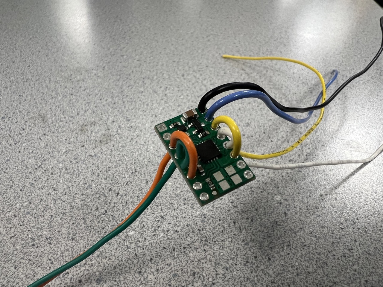
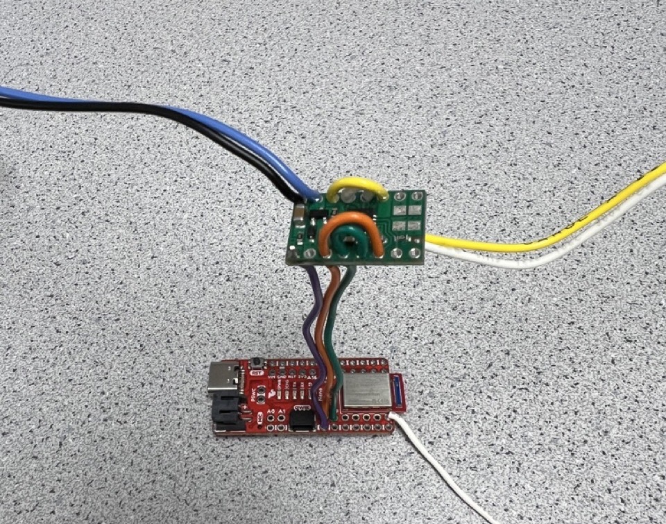
The next step involves testing the connection using an external power supply. The motor driver, as per the datasheet, can operate within a voltage range of 2.7 V to 10.8 V. Since our battery outputs at 3.7 V, we've set the external power supply to match this voltage. We also connected the motor driver to the Artemis board to generate a PWM signal for control. Specifically, pins A2 and A3 on the Artemis board are linked to AIN1 and BIN2 on the motor driver to transmit the PWM signal. Additionally, the GND pin on the Artemis board is connected to the GND pin on the motor driver. The connection setup is illustrated in the figure below.
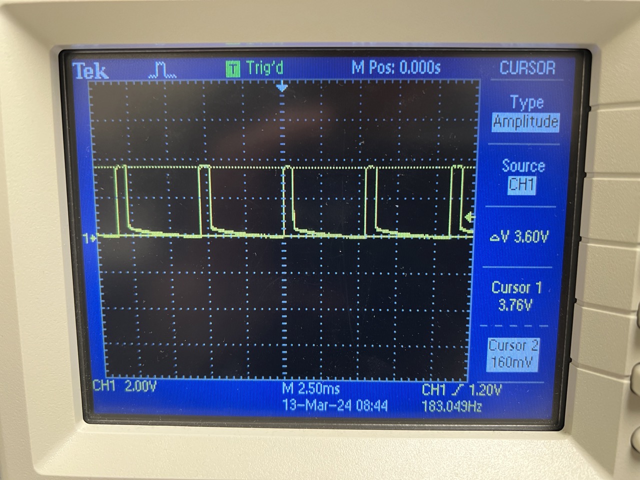
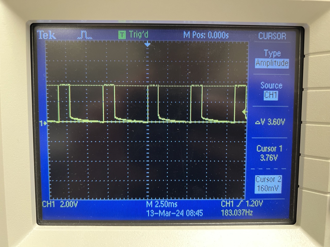
We utilized the analogWrite commands to generate PWM signals and measured the power at the motor driver output using an oscilloscope. The code snippet is shown below. We conducted tests with different PWM values ranging from 32 to 255. The results are depicted in the figure below.
#define leftforward A2
#define leftbackward A3

void setup() {
pinMode(leftforward, OUTPUT);
pinMode(leftbackward, OUTPUT); }

void loop() {
analogWrite(leftforward, 64);
analogWrite(leftbackward, 0); }
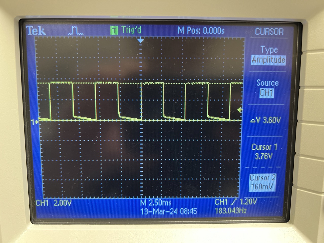
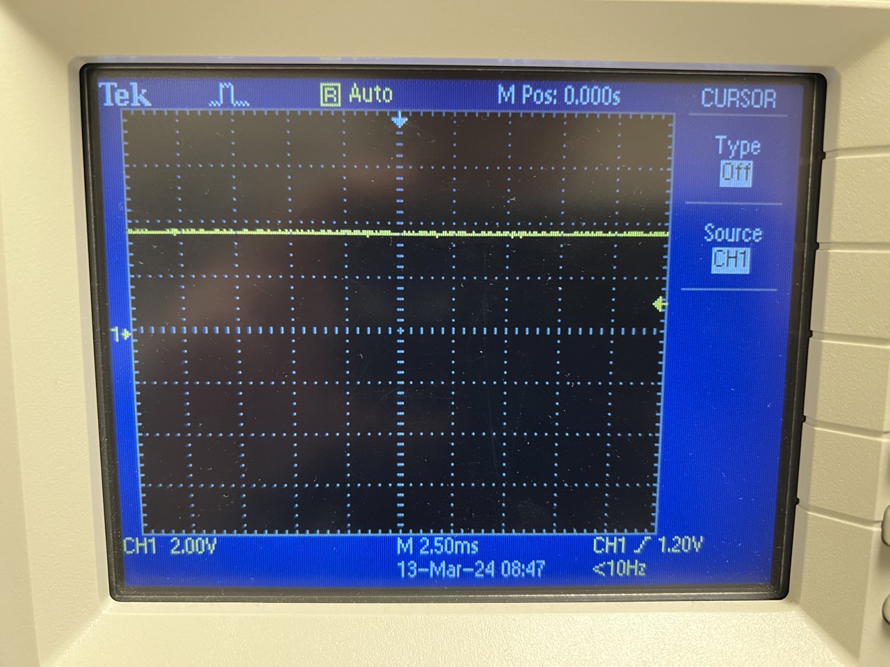
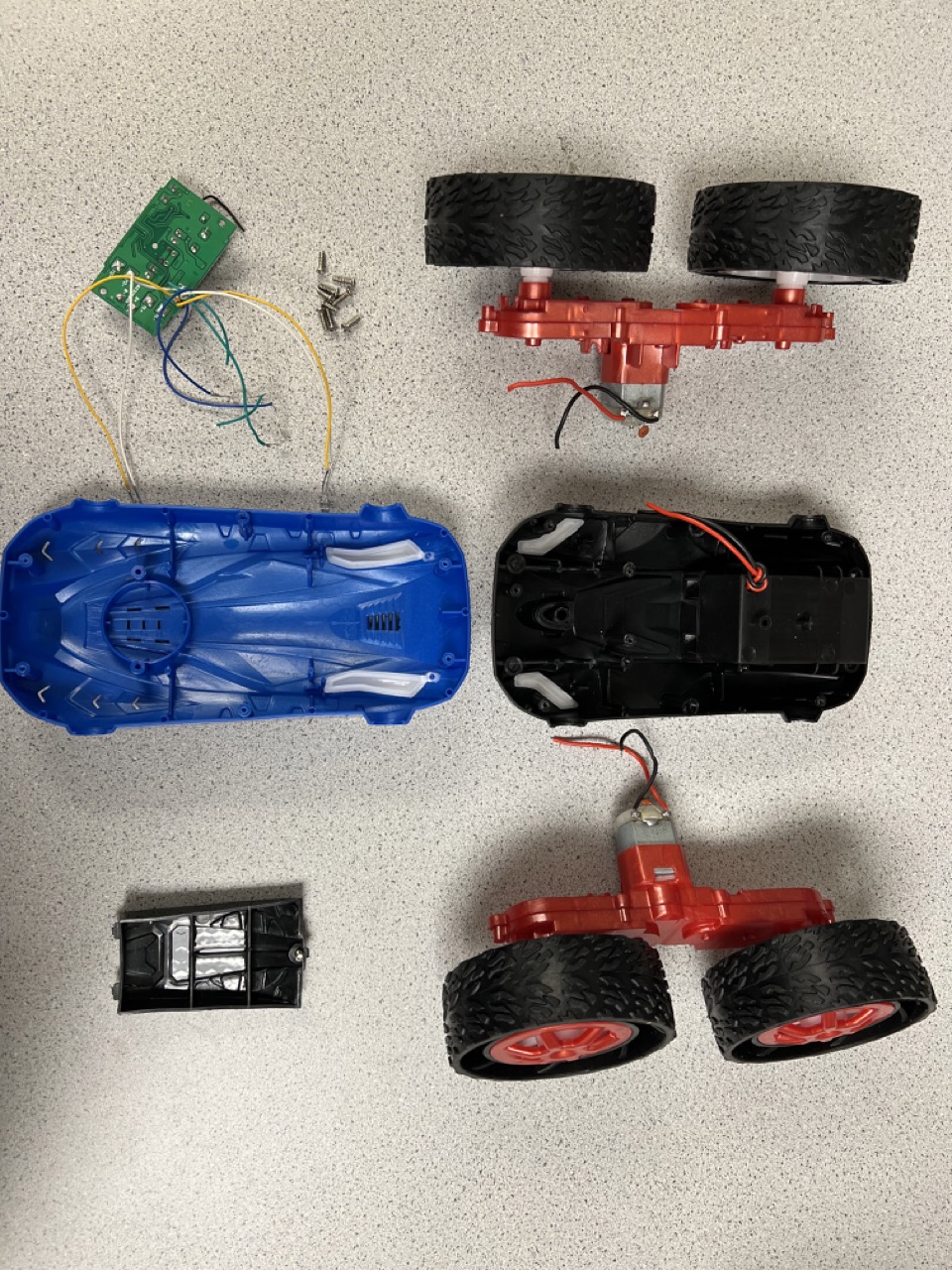
Next, we disassembled the Force1 RC car and cut the original remote control PCB. The disassembled car is shown in the accompanying figure.
Then we connected the output of the motor driver to the motor in the Force1 car and tested it by sending a PWM signal from the Artemis board. The code for generating the PWM signal remains unchanged from the previous example. According to this video, the wheels spin normally in both directions when the motor driver is powered by the 850mAh battery.
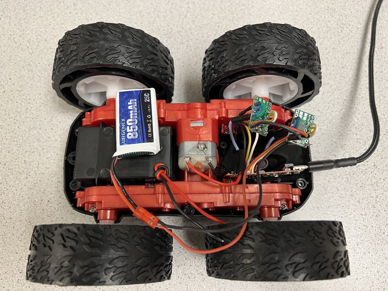
We repeated the previous steps for the other motor driver and motor. And the final wiring is shown in the figure below. We also tested both motors with different PWM signals from the Artemis board. We powerd the Artemis board and motor drivers from separate batteries to isolate electrical noise and prevent potential damage to sensitive components. This setup also allows for optimized voltage and current supply to each component, ensuring stable and reliable operation.
Sensor Assembly
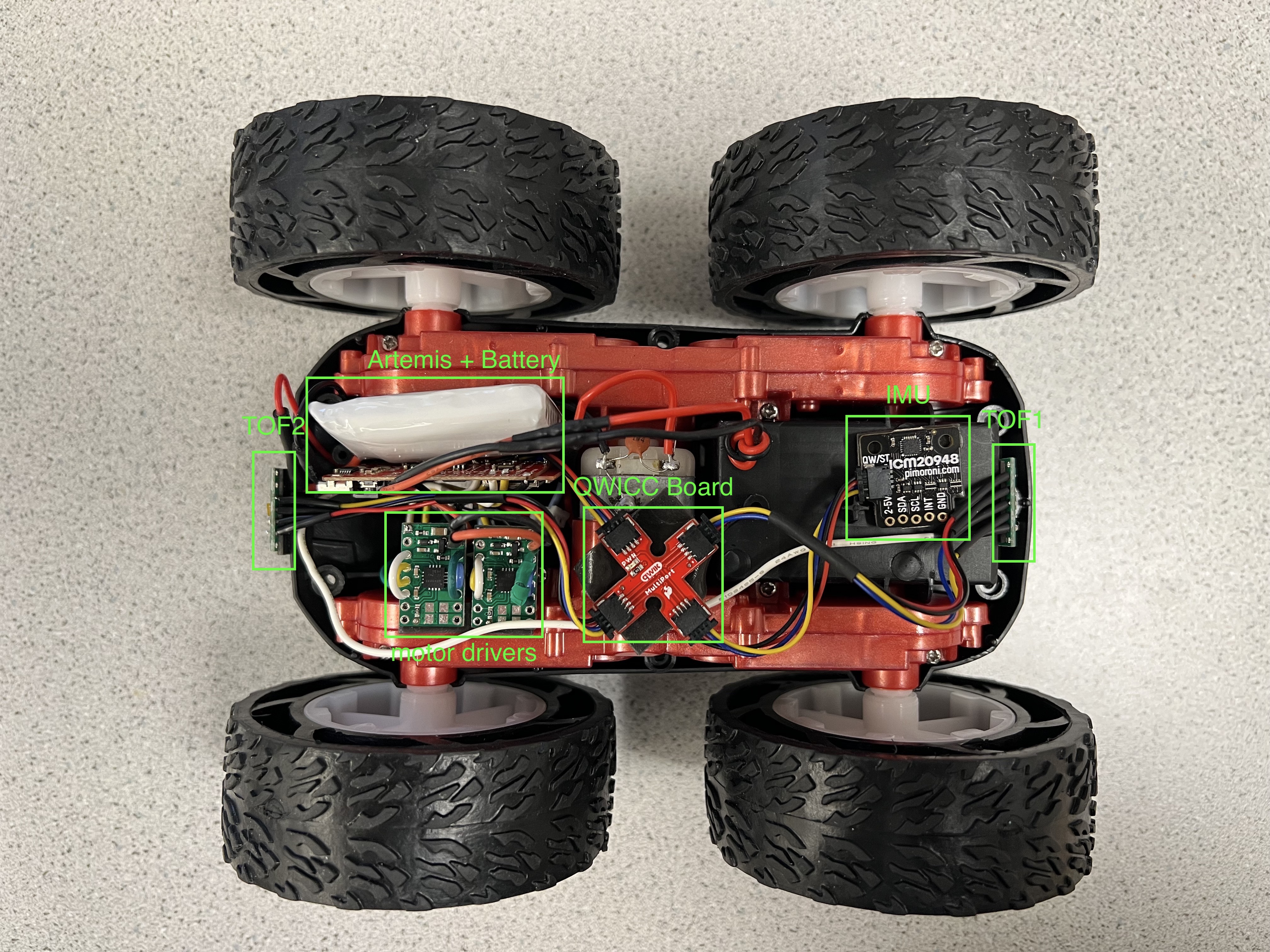
After the motor and motor drivers are tested, the different sensors from the previous labs are also installed in the car. The figure below is the car with everything hooked up.
Testing
After installing everything inside the car chassis, we tried running the car on the ground. As shown in the code snippet below, both motor will move forward with PWM value as 64. In addition, we added a timer such that the motor will turn off automatically after the program starts for four seconds.
#define leftforward A2
    #define leftbackward A3
    #define rightforward 11
    #define rightbackward 12

    unsigned long startTime;
    const unsigned long TOTAL_DURATION = 4000;

    void setup() {
      // put your setup code here, to run once:
    pinMode(leftforward, OUTPUT);
    pinMode(leftbackward, OUTPUT);
    pinMode(rightforward, OUTPUT);
    pinMode(rightbackward, OUTPUT);
    startTime = millis();
    }

    void loop() {
    if(millis() - startTime <= TOTAL_DURATION){
      analogWrite(leftforward, 64);
      analogWrite(leftbackward, 0);
      analogWrite(rightforward,64);
      analogWrite(rightbackward,0);
    }
    else{
      analogWrite(leftforward, 0);
      analogWrite(leftbackward, 0);
      analogWrite(rightforward,0);
      analogWrite(rightbackward,0);
      }
    }
The video below shows that the car moves as expected.
Explore the lower limit in PWM value
45,33
case GET_PWM_VALUE:
    int pwm_value;
    // Extract the next value from the command string as an integer
    success = robot_cmd.get_next_value(pwm_value);
    if (!success)
        return;

    Serial.print("PWM value is ");
    Serial.println(pwm_value);
    analogWrite(leftforward,pwm_value);
    analogWrite(leftbackward,0);
    analogWrite(rightforward,pwm_value);
    analogWrite(rightbackward,0);
    break;